


Views: 0 Author: Site Editor Publish Time: 2026-09-08 Origin: Site


Table of Contents
Guessing power requirements leads to catastrophic downtime during outages or wasted capital on oversized equipment. Facility managers and electrical engineers face high operational stakes when selecting backup power. Getting the sizing wrong introduces dual risks that jeopardize both the facility's infrastructure and the equipment itself.
Undersizing a unit causes severe voltage dips, motor stalls, and breaker trips during peak surges. When the alternator cannot handle the inrush current of heavy machinery, sensitive electronics reboot and UPS systems drain prematurely. Conversely, oversizing leads to wet stacking, inefficient fuel consumption, and accelerated engine wear due to low operating temperatures. Operating outside the optimal load band destroys engine longevity and inflates maintenance schedules.
Establishing reliable, compliant backup power requires a systematic, math-based framework. Calculating exact power requirements involves analyzing running kW, maximum starting loads, aggregate power factor, and specific electrical phase configurations. This methodology ensures the selected equipment handles transient spikes while maintaining a healthy continuous load profile.
Calculate total running wattage (kW) alongside maximum motor starting surges, which can spike 3 to 6 times higher than the running load.
Differentiate between actual power (kW) and apparent power (kVA) by factoring in the facility’s specific Power Factor (PF), typically 0.8 for industrial applications.
Match the generator's phase (single-phase vs. three-phase) and voltage precisely to the facility's existing electrical service, including specific Wye (Y) or Delta configurations.
Incorporate a 20–25% reserve capacity margin (Safety Margin) to accommodate future facility expansion and prevent the diesel generator from running at 100% continuous load.
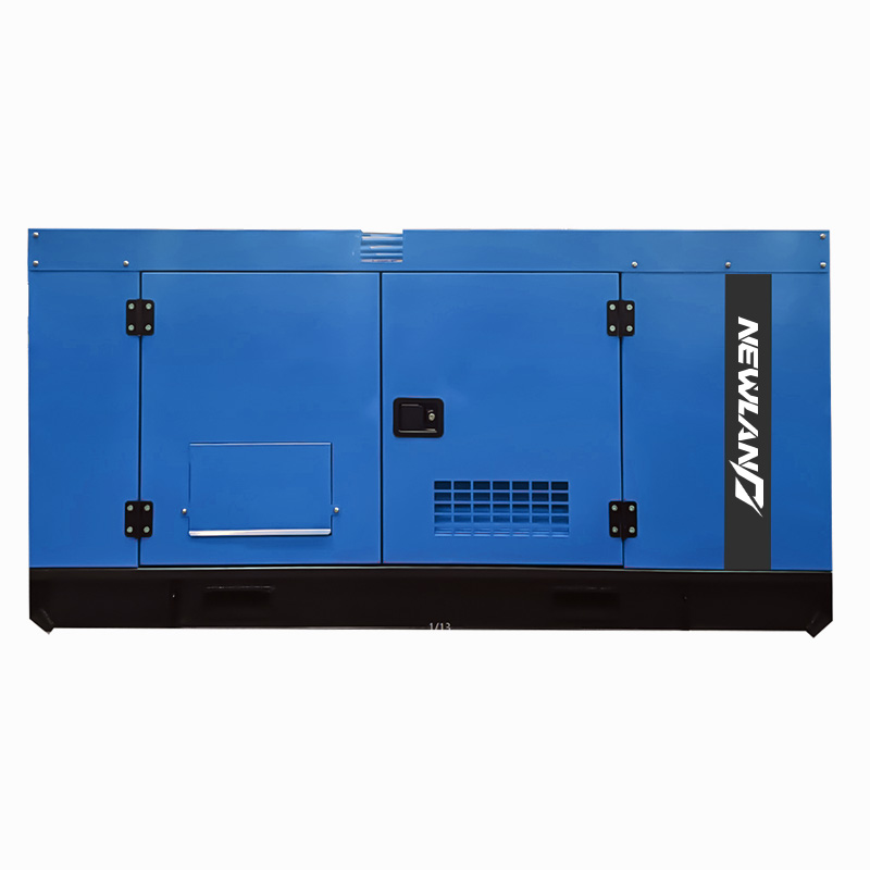
A successfully sized generator maintains stable voltage under heavy transient loads, operates efficiently within its optimal thermal range, and meets local emissions standards. Achieving these success criteria requires understanding exactly how sizing errors manifest in physical equipment failure on the facility floor.
Voltage drop occurs when the surge demand from connected equipment exceeds the alternator's capacity to maintain magnetic flux. When heavy industrial motors start, they require massive inrush current to overcome static friction. If the alternator cannot supply this current, the system voltage plummets rapidly.
This sudden voltage dip disrupts operations across a facility. Sensitive electronics, programmable logic controllers (PLCs), and IT infrastructure will reboot or shut down entirely. Variable Frequency Drives (VFDs) will detect the under-voltage condition and trip offline to protect themselves. Uninterruptible Power Supply (UPS) systems will sense the unstable voltage and refuse to transfer back to generator power, draining their batteries until the facility goes dark.
Furthermore, heavy motors that lack sufficient starting current will stall. A stalled motor draws locked rotor current continuously. This rapidly overheats the internal stator windings, melting the insulation and causing a dead short that destroys the motor.
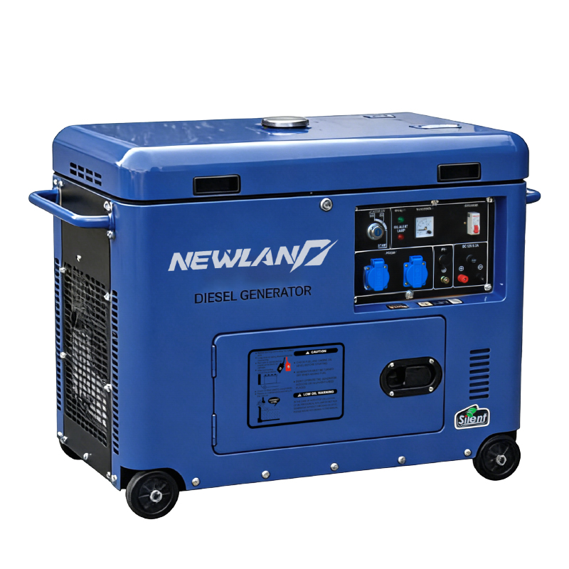
Many facilities intentionally oversize their backup power under the false assumption that bigger is safer. Running a diesel engine below 30% of its rated capacity prevents the cylinder temperatures from reaching their optimal operating range. This low-temperature operation leads directly to a mechanical condition known as wet stacking.
Wet stacking is the accumulation of unburned fuel, lubricating oil, and carbon buildup in the exhaust system. Because the cylinder rings do not expand fully at low temperatures, unburned fuel washes the lubricating oil off the cylinder walls. The engine begins to slobber thick, dark liquid from the exhaust manifold. This condition glazes the cylinder walls, reduces piston ring sealing, and drastically lowers engine compression. Over time, wet stacking destroys engine efficiency and mandates expensive load bank testing to burn off the carbon.
Sizing Error | Primary Symptoms | Mechanical Impact | Operational Consequence |
|---|---|---|---|
Undersizing | Severe voltage dips, breaker trips, dimming lights | Alternator overheating, motor winding failure | Facility blackouts, damaged IT infrastructure, stalled production lines |
Oversizing | Exhaust slobber, low operating temperatures, excessive smoke | Cylinder glazing, loss of compression, carbon buildup | Increased maintenance costs, shortened engine lifespan, emissions violations |
Accurate sizing begins with a comprehensive audit of all facility equipment. You must document every piece of machinery that will draw power during an outage. This includes HVAC units, air compressors, industrial pumps, lighting panels, server racks, and fire suppression systems.
The most critical distinction in load auditing is the difference between running current and starting current. Full Load Amps (FLA) represents the steady current drawn by a motor during normal, continuous operation. Locked Rotor Amps (LRA) represents the massive initial surge required to start that motor from a standstill.
When a large induction motor starts across the line, its LRA can spike 3 to 6 times higher than its FLA. For example, a 100 horsepower motor might draw 124 amps while running at 480V, but it will demand over 700 amps for the first few seconds of startup. If you size a generator based only on FLA, the unit will trip its main breaker the moment a heavy compressor kicks on. You must sequence your loads and size the alternator to handle the LRA of the largest motor starting simultaneously with the base facility load.
Not all electrical loads consume power with the same efficiency. Resistive loads, such as incandescent lighting and simple electrical heaters, convert almost 100% of their current into useful work. Inductive loads, such as transformers and electric motors, require a magnetic field to operate, which draws reactive power.
Inventory every significant load or load group with its specific running kW and individual power factor before applying a facility-wide average. Failing to account for individual power factors leads to inaccurate apparent power calculations. This results in an undersized alternator that overheats under heavy inductive loads.
The operational profile dictates the required engine durability and alternator size. Manufacturers rate equipment based on strict ISO 8528 standards for application types. You must select the correct rating to ensure warranty compliance and mechanical reliability.
Rating Type | Operational Profile | Overload Capability | Typical Application |
|---|---|---|---|
Standby Power | Emergency backup during utility outages. Max 200-500 hours/year. | None. Do not exceed nameplate rating. | Hospitals, commercial office buildings, retail stores. |
Prime Power | Primary source of electricity. Unlimited hours at variable loads. | 10% overload permitted for 1 hour every 12 hours. | Remote mining sites, off-grid construction, oil rigs. |
Continuous Power | Steady, unchanging load 100% of the time. | None. Designed for constant base load. | Data centers, continuous manufacturing processes, utility base loading. |
Understanding how to size a diesel generator requires a firm grasp of the relationship between real power, apparent power, and electrical efficiency. These metrics dictate both the engine size and the alternator size.
Kilowatts (kW) represent Real Power. This is the actual power consumed by the equipment to perform physical work, such as turning a pump impeller or generating heat. The engine's physical horsepower dictates the maximum kW the unit can produce. If the kW demand exceeds the engine's capability, the engine will bog down and stall.
Kilovolt-Amperes (kVA) represent Apparent Power. This is the total power drawn from the generator, encompassing both the real power (kW) and the reactive power (kVAR) required to magnetize inductive loads. The alternator's physical size, copper windings, and thermal capacity dictate the maximum kVA. If the kVA demand exceeds the alternator's capability, the windings will overheat and melt.
The standard conversion formula is: kVA = kW / Power Factor.
Power Factor (PF) measures electrical efficiency on a scale from 0 to 1.0. A purely resistive load has a PF of 1.0. A heavily inductive load might have a PF of 0.6. When calculating aggregate demand for a facility with variable power factors, you must determine the total real power and total reactive power separately before combining them.
For standard industrial applications utilizing three-phase power, the industry universally applies a Power Factor of 0.8 to rate the equipment. Therefore, a 1000 kVA unit will produce 800 kW of real power (1000 × 0.8 = 800). If your facility has a highly corrected power factor (e.g., 0.95 due to capacitor banks), you must ensure the engine has enough horsepower to support the higher kW output without stalling.
Electrical panels and machinery require specific voltage and phase configurations. The backup power source must natively match the facility's existing electrical service to ensure safe and efficient operation. You cannot easily change a generator's phase output in the field without significant efficiency losses.
Single-phase power is standard for residential homes and light commercial buildings. It delivers power through a single alternating current wave. Three-phase power delivers power through three overlapping alternating currents. This provides a smoother, more continuous flow of energy required by heavy machinery and large induction motors.
Attempting phase conversion using rotary phase converters or variable frequency drives (VFDs) between the generator and the load is highly inefficient. It introduces unnecessary points of failure and massive harmonic distortion. The alternator must be wound specifically for the phase configuration of the facility.
Industrial facilities utilize various standard voltages depending on their regional grid and heavy equipment requirements. Beyond the voltage numbers, you must identify the specific wiring configuration at the main distribution panel.
Wye (Y) Configuration: Features a central neutral wire connected to a common star point. This allows the system to serve both line-to-neutral loads (like standard 120V wall outlets) and line-to-line loads (like 208V motors) simultaneously. Example: 120/208Y.
Delta Configuration: Typically lacks a neutral wire and is designed strictly for heavy, balanced motor loads. Connecting single-phase equipment to a Delta system without a proper isolation transformer will destroy the equipment.
Configuration Type | Neutral Wire Included? | Primary Application | Common Voltage Examples |
|---|---|---|---|
Single-Phase | Yes | Residential, Light Commercial, Basic Lighting | 120/240V |
Three-Phase Wye (Y) | Yes | Mixed Industrial (Motors + Office Outlets) | 120/208V, 277/480V |
Three-Phase Delta | Usually No | Heavy Industrial, Dedicated Motor Loads | 240V Delta, 480V Delta |
If a facility operates with mixed voltage requirements, step-up or step-down transformers must be integrated into the distribution system. However, transformers introduce their own inrush current requirements known as magnetizing inrush. This initial surge must be factored into the sizing calculations to prevent breaker trips upon transfer.
With the load inventory complete and the phase requirements identified, you can apply standard electrical formulas to determine the exact capacity required. This prevents the operational failures associated with rough estimations.
First, calculate the Full Load kW based on the total amperage draw of your facility. You must pull these amperage numbers directly from equipment nameplates or a recent electrical load study.
For Single-Phase systems, the calculation is straightforward:Total Amps × Supply Voltage ÷ 1,000 = Full Load kW
For Three-Phase systems, you must account for the three overlapping power waves by multiplying by the square root of 3 (approximately 1.732):Total Amps × Supply Voltage × 1.732 ÷ 1,000 = Full Load kW
Once you have the Full Load kW, divide it by the facility's power factor (usually 0.8 for three-phase) to find the required kVA.
Running any engine at 100% of its maximum capacity continuously will cause rapid overheating and premature failure. Industry best practices mandate a reserve capacity, also known as a safety margin, of 20% to 25%.
Calculate the final requirement using a safety multiplier:kVA_required = (kW_load / PF) × (1 + M_safety)
A simplified approach for final sizing is:Generator Size = Full Load kW + Reserve Capacity (typically 25%)
This reserve capacity accommodates future facility expansion, handles unexpected transient load spikes, and ensures the engine operates comfortably within its 70–80% optimal thermal band.
Consider a manufacturing plant with a 480V, 3-phase electrical service. The facility audit reveals a total running draw of 400 Amps, which includes heavy motor loads and a standard industrial power factor of 0.8.
Calculation Step | Formula Applied | Result |
|---|---|---|
1. Calculate Total Watts | 400 Amps × 480 Volts × 1.732 | 332,544 Watts |
2. Convert to kW | 332,544 Watts ÷ 1,000 | 332.5 kW |
3. Convert to kVA (Apparent Power) | 332.5 kW ÷ 0.8 PF | 415.6 kVA |
4. Add 25% Safety Margin | 415.6 kVA × 1.25 | 519.5 kVA |
Based on this calculation, the facility requires a unit rated for at least 520 kVA. Depending on manufacturer availability, a 550 kVA unit would be the appropriate selection to ensure robust motor starting capability without risking wet stacking during lighter load periods.
Nameplate ratings on equipment spec sheets represent performance under standard test conditions. These conditions are usually defined as sea level elevation and 77°F (25°C) ambient temperature. Real-world site conditions require derating the equipment to account for environmental variables that degrade engine performance.
Diesel engines rely on oxygen to combust fuel. At high altitudes, the air is thinner and contains less oxygen. This lack of oxygen directly reduces engine horsepower. Similarly, high ambient temperatures reduce air density, leading to the same loss of combustion efficiency. Turbochargers help mitigate altitude loss by forcing more air into the cylinders, but they do not eliminate the derating requirement entirely.
Standard derating formulas require deducting a specific percentage of the unit's capacity based on elevation and heat. A common rule of thumb is to deduct 3% of the rated capacity for every 1,000 feet above sea level, and deduct 1% for every 10°F above 77°F. If you install a 500 kW unit in Denver, Colorado (elevation 5,280 feet), the altitude alone reduces its actual output by over 15%, dropping its effective capacity to roughly 420 kW.
Environmental Factor | Standard Derating Penalty | Physical Cause |
|---|---|---|
Altitude | ~3% per 1,000 feet above sea level | Lower air pressure reduces oxygen mass entering the cylinders. |
Ambient Temperature | ~1% per 10°F above 77°F | Hot air is less dense, reducing oxygen concentration for combustion. |
Humidity | Varies (typically minor) | Water vapor displaces oxygen in the intake air. |
Physical site constraints dictate the type of enclosure and cooling system required. Units installed in tight urban spaces or residential zones require sound-attenuated enclosures to meet strict municipal noise ordinances. These heavy enclosures restrict physical airflow, which must be accounted for in the radiator cooling calculations.
Ensure the installation site provides adequate clearance for maintenance access. You must provide sufficient fresh air intake for combustion and cooling. Proper exhaust routing is mandatory to prevent carbon monoxide pooling near building HVAC intakes or pedestrian walkways.
Proper sizing is only the first step. Long-term reliability depends on rigorous maintenance protocols and strict adherence to operational safety standards. A perfectly sized Diesel Generator will still fail if neglected.
Routine load bank testing is mandatory for any unit that occasionally runs below its 30% capacity threshold. A load bank applies an artificial, purely resistive load to the alternator, forcing the engine to work at full capacity. This process raises exhaust temperatures, burns off accumulated carbon deposits, cures wet stacking, and verifies that the cooling system can handle a 100% load during a real emergency.
Operators must practice safe load removal procedures. Disconnecting massive industrial loads instantaneously can cause severe voltage spikes that damage the alternator's automatic voltage regulator (AVR). Loads should be stepped down sequentially before shutting the unit down to allow the engine to cool properly.
Additionally, pre- and post-operational fluid inspections are critical. Cycling heavy loads stresses internal engine components. Routine oil checks verify viscosity and check for coolant or fuel contamination. Identifying these issues early prevents catastrophic engine seizure during extended outages.
Local air quality regulations heavily influence equipment selection. The Environmental Protection Agency (EPA) categorizes non-road diesel engines into Tier ratings based on their emissions output. Tier 3 units are often acceptable for stationary emergency standby applications. However, prime power applications frequently require Tier 4 Final compliance.
Tier 4 Final units utilize advanced exhaust aftertreatment systems. These include Diesel Particulate Filters (DPF) and Selective Catalytic Reduction (SCR) systems requiring Diesel Exhaust Fluid (DEF). These systems add physical bulk, increase initial capital costs, and require specific maintenance routines to prevent exhaust backpressure faults. If a DPF clogs because the engine is consistently underloaded, the engine control module will derate the power output or shut the unit down entirely.
Consult with a certified electrical engineer to perform a comprehensive site load analysis, documenting exact LRA and FLA for all critical machinery.
Verify your facility's exact voltage and phase configuration at the main distribution panel to prevent costly mismatch errors.
Calculate your required kVA using the 1.732 multiplier for three-phase systems and apply a strict 25% safety margin.
Request detailed specification sheets from top-tier manufacturers, paying close attention to alternator surge capabilities and EPA Tier compliance.
Establish a schedule for annual load bank testing and routine fluid analysis to protect your capital investment.
A: Oversizing causes the engine to run below its optimal operating temperature. This leads to wet stacking, where unburned fuel and carbon accumulate in the exhaust system. Over time, this reduces engine efficiency, glazes cylinder walls, drastically increases maintenance costs, and shortens the equipment's lifespan.
A: For single-phase systems, multiply total amps by the supply voltage, then divide by 1,000. For three-phase systems, multiply total amps by the supply voltage, multiply that result by 1.732, and then divide by 1,000 to find the Full Load kW.
A: Three-phase power consists of three distinct alternating currents that overlap to provide continuous power. The multiplier 1.732 is the square root of 3, which mathematically accounts for the phase geometry and voltage relationship between the three separate lines in the electrical system.
A: In commercial and industrial applications utilizing three-phase power, the standard power factor used for rating equipment is 0.8. This accounts for the reactive power drawn by inductive loads like electric motors and transformers, ensuring the alternator is sized correctly for the apparent power demand.
A: Industrial electric motors require massive inrush current to overcome static friction when starting. This Locked Rotor Amp (LRA) draw can spike 3 to 6 times higher than the motor's normal running current. The alternator must be sized to handle this maximum starting surge without dropping voltage.
A: Wet stacking is the buildup of thick, dark, unburned fuel and carbon in the exhaust system caused by running the engine at too low of a temperature. It is prevented by properly sizing the unit to run at 70-80% capacity and performing routine load bank testing to burn off deposits.


